I am implementing a simple (post process) distortion shader: the image in render texture A is distorted by the displacement in render texture B. The material has two texture samplers, one for render texture A and one for render texture B. The fragment shader is just the following lines:
I have precision issue with this shader and it seems to me that the material is ignoring the sampler filter settings: linear / nearest has no influence in the output.
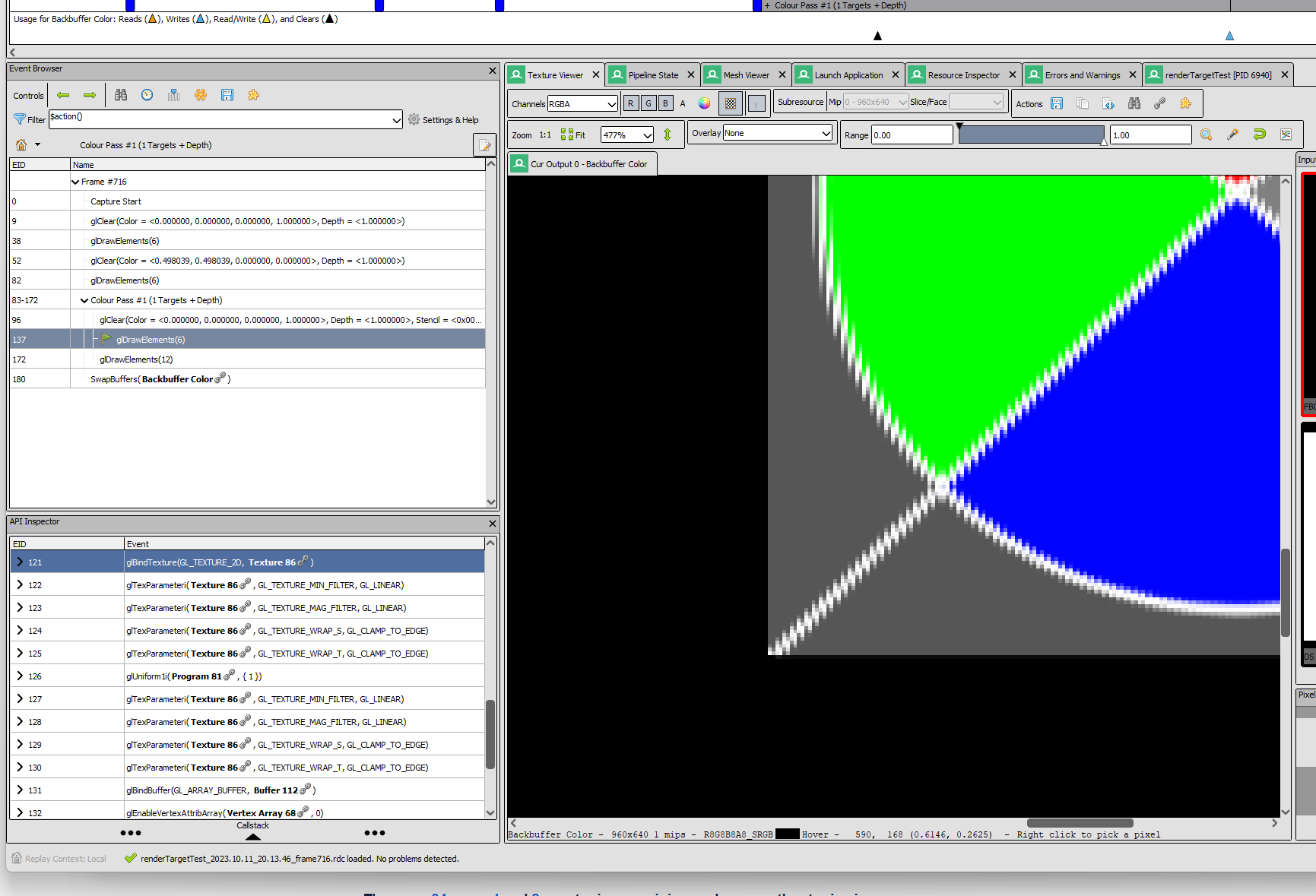
The shader looks fine to me, so I think we need more information to give any advice here. Do you have a repro? Or can invite to the project? Or at least a screenshot?
Here are screenshots of
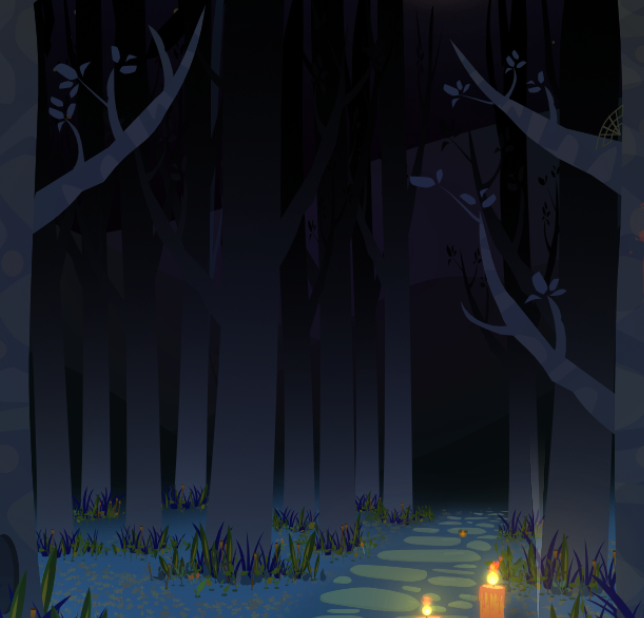
(1) render target A = non distorted image
(2) render target B = displacement image (in the channel red and green)
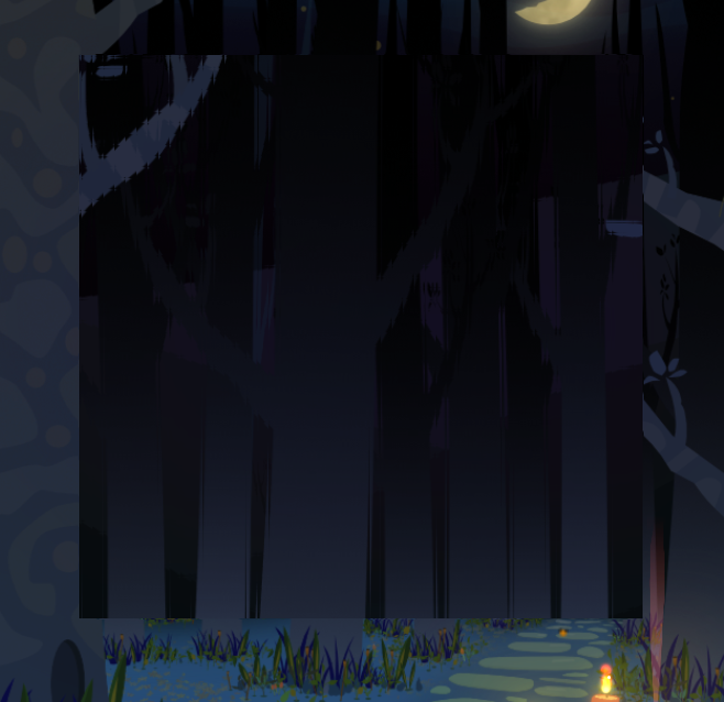
(3) the result of the shader with input (1) and (2).
As you can see in (3) there are very evident artifacts.
Note that the result in (3) does NOT change if the min/mag filter is LINEAR or NEAREST, and this is somehow surprising to me. I have tried to change both: (a) the filter settings in the material associated with the shader and (b) the filter settings in the options when creating the render targets A and B.
var_texcoord0 varies in [0,1] x [0,1] and are the texcoord of a quad covering the entire screen
dist is computed as in the shader where the sampled texture tex1 has values in [0,1]x[0,1]; only the red and green channels are used as displacement in x and y, respectively.
dist_scale is used only to compensate the aspect ratio of the render targets A and B and these two have the same resolutions (the same of the window) and can be assumed to be (1,1).
My conclusion is that the engine is using NEAREST as min/mag filter (for render target B, at least) and this explains the artifacts.
In the game window you see from left to right: the non-deformed sprite, the deforming displacement map, the deformed sprite. Note that in main.script the displacement map is drawn with an alpha of 0.5 to reduce the displacement. Moreover in the render the constant dist.xy is set to (1.0, -0.1) to compensate the aspect ratio of the window; finally the source sprite in main.collection is flipped horizontally. However all these are just details.
As you see, the displaced image is jagged. And, I am more and more convinced that the engine is sampling the displacement render target with filter NEAREST. This explain mathematically why the lines are jagged. The filter is set to LINEAR both when creating the render targets and in the post process material.
@jhonny.goransson Once again I returned to this issue and this time I finally fixed it!
It was a problem about the image format of the texture storing the distortion data. Or, at least, I understand it this way. Let me write shortly some more information, for someone else that could be interested in this.
I was using graphics.TEXTURE_FORMAT_RGBA. This resulted in normalized unsigned 8 bits per channel: this means that the values stored in the color channel are in the interval [0, 255] and that they are converted to [0.0, 1.0] when the texture is sampled.
If the filter is set to linear, the sampled values are linearly interpolated among adjacent pixel data. BUT it seems that this interpolation happens in the same format of the texture being sampled!!! So a very large quantization error is present for small values since the texture format was 8bit per channel. Changing the texture format to something using floating point data fixed the issue.
Some side notes.
For my particular need I am now using graphics.TEXTURE_FORMAT_RG16F as texture format. Please note that this particular format is not listed in the API documentation for render.render_target(); but everything seems to run fine!
The texture format graphics.TEXTURE_FORMAT_RGBA does not specify the bitdepth and, according to this page https://www.khronos.org/opengl/wiki/Image_Format, an openGL driver is free to pick a bitdepth. On the other hand it seems to me that some formats with the explicit bitdepth, for example TEXTURE_FORMAT_RGBA8, is not defined in the graphics module. I would suggest to define these, so that one can choose the bitdepth.