Clipping Tilemaps

What you can do is set the fragment program alpha to 0.0 based on if it is inside of the current circle sector or not. Pie chart shaders could give you an idea of how to select a sector of a circle https://www.shadertoy.com/view/MtKcDt

So for each set of rendering it would have its own constants when drawing each area you want to clip.

local constants_1 = render.constant_buffer()
constants.sector = vmath.vector4(sector_start, sector_end, 1, 1) 
render.draw(self.pred_1, constants_1)
...

You cannot recycle render constant buffers, use a unique one for each sector.

Okay, I think it looks like the missing piece that took me so long to digest this is that I tried starting at the wrong end. I was looking at the vertex and fragment programs, trying to figure out how they know what they’re working on; if I had started with making the material, I would have seen that the vertex and fragment programs are called by the material.

I think this means that I only need to make one vertex program and one fragment program, and differentiate between the three areas by the vertex and fragment constants on the material itself? I’m not sure exactly how that might relate to what you said about constant buffers, but I think I have enough info now to learn by failing at the very least.

EDIT: And it looks like the scene and sprites are the only places that define the material, so it looks like I will need to pass the correct material to the scene and the sprites contained therein through the collection factories and game objects.

Where is that code snippet intended to be used, exactly?

In the render script. It was referenced by the render file listed in the game.project file. Look at the lines related to defining / drawing the different render predicates / tags. You list the tags of a material at the bottom of the material file.

I’m having trouble getting it to draw if I change the tag, even without trying to change anything.

I set the tag on the material to character_1, added the line

self.character_1_pred = render.predicate({"character_1"})

to init(), and trimmed down your snippet to what seems to be the bare minimum:

render.draw(self.character_1_pred)

and the material doesn’t show up unless I add the tile tag back to it.

To confirm

  1. Make new sprite material, assign it to the
  2. Edit to modify tag (tile -> character_1)
  3. Add tag to top of render script at top and draw it when other tags are drawn

Though I realize you want to be sending 3 camera positions to the render script either with messages or via a shared Lua module. Then I think you could redraw the scene with the same render target giving it different values for its radial clipping material along with the different camera offsets.

Does it need to be told how to draw a new predicate, or should it be enough to just call draw on the predicate?

Okay, so it turns out the new render script works so much better if you actually remember to set the Render in game.project to it.

Time for my nap.

3 Likes

Okay, I give up. I can’t figure out any values to give the constant buffer you use that make anything happen. Is there any kind of tutorial or info on using this that you could point me to? The Defold manuals and API reference don’t really explain any of this at all.

Okay, I’m thinking now that those must be constants provided to the vertex and fragment programs. I’ve figured out how to draw lines on the screen, I think I should be able to work my way up to figuring out the shadertoy sample from there.

2 Likes

Please keep going with trying to get this to work!

I know for sure it’s possible even though I’m not aware if anyone has done this specific thing yet.

Please post notes of specific official manuals you think are not clear enough in relation to the issues you brought up.

Well, for starters, the issue I’m having right now is that, while the API does talk about creating constant buffers, I’m not seeing any mention of how to reference them either there or in the Shader manual, so creating them isn’t doing a whole lot of good without knowing how to read them.

Edit: I’m checking to see if I can find the window size from the fragment program anywhere, but so far no luck.

Also, I think it sounds like they don’t have any inherent meaning other that what you use them for; so I could conceivably code the center coordinates of the circle in the vec4 with the start and end arcs, right? Something like vec4(center_x, center_y, sector_start, sector_end)? Or is there some reason I wouldn’t want to do that?

I’m not seeing any mention of how to reference them

A short manual for render constant buffers and how they related with materials / drawing predicates would be useful. I’ll answer some of what you mention even if it’s clear to you now.

You want to edit the material and fragment program to add the constants you are interested in. See how the tint constant is setup for the builtin sprite material. Unused constants are automatically stripped from shader programs.

You can pass the view size of the window as an additional constant when drawing a predicate. The code sample I posted above is an example of using constants.

local constants_1 = render.constant_buffer()
constants.sector = vmath.vector4(sector_start, sector_end, 1, 1) 
render.draw(self.pred_1, constants_1)

So you could do

local clip_constants = render.constant_buffer()
local window_view_size = vmath.vector4()
window_view_size.x = render.get_window_width()
window_view_size.y = render.get_window_height()
render.draw(self.pred_tiles, clip_constants)

(I’m pretty sure render.get_window_width() etc is for the actual view size of the window but don’t remember for sure atm, DefOS has a get view size function too.)

Then in a “pred_tiles” predicate it would be sent a window_view_size vec4 and you would be able to use it similar to how tint is used in sprites.

You can also update constants directly on for example sprite components but that breaks batching and in this case isn’t useful.

Also, I think it sounds like they don’t have any inherent meaning other that what you use them for

Right, vec4s are just the container being always used for right now. You don’t have to use all of the fields.

Something like vec4(center_x, center_y, sector_start, sector_end)

Yes, you can do that.

Ooh, another missing API reference documentation: are vmath operators a thing?

I see functions for dot() and stuff like that, but can I, for example, add or subtract vectors of the same size? Or divide a vector by a constant, so I don’t have to do fun constructs like:

-- wordy:
local center = vmath.vec4(viewport.x / 2, viewport.y / 2, 0, 0)
-- better:
local center = viewport / 2

Yes, you can do those.

function init(self)
	local viewport = vmath.vector4(800,600,0,0)
	local center = viewport / 2
	pprint(center)
	center = center - center
	pprint(center)
	center = center + viewport
	pprint(center)
end

DEBUG:SCRIPT: vmath.vector4(400, 300, 0, 0)
DEBUG:SCRIPT: vmath.vector4(0, 0, 0, 0)
DEBUG:SCRIPT: vmath.vector4(800, 600, 0, 0)

Lovely! Thanks for all your help! I’ve still got a bunch of mathy stuff to make sure I’m getting right (I think I’ve identified the important pieces from the shader you linked, but I like to make sure I understand what I’m inputting as much as possible), but I think I’ve got the important foundational stuff laid, at long, exhausting, last.

1 Like

Looking forward to seeing more about your project!

Proof of concept!

It’s kind of hard to tell on the bottom - the next step is obviously going to be adding separating lines - and I obviously haven’t applied it to the sprites yet, but we have our 3-pane radial split screen. Huzzah!

Here’s the fragment code:

varying mediump vec4 position;
varying mediump vec2 var_texcoord0;

uniform lowp sampler2D texture_sampler;
uniform lowp vec4 tint;
uniform lowp vec4 window_size;
uniform lowp vec4 sector;

uniform float PI = 3.1415926535897932384626433832795;

void main()
{
	// Pre-multiply alpha since all runtime textures already are
	lowp vec4 tint_pm = vec4(tint.xyz * tint.w, tint.w);
	
	// New code
	vec2 center = sector.xy;
	float right_edge = window_size.x;
	float start = sector.z;
	float end = sector.w;

	vec2 startVec = vec2(-cos(PI * start), sin(PI * start));
	vec2 endVec = vec2(-cos(PI * end), sin(PI * end));
	
	if (right_edge < gl_FragCoord.x || distance(gl_FragCoord.xy, center) <= 3)
	{
		gl_FragColor = vec4(0,0,0,0);
	}
	else
	{
		vec2 p = gl_FragCoord.xy - center;
		if (dot(p, startVec) > 0 && 0 > dot(p, endVec))
		{
			gl_FragColor = texture2D(texture_sampler, var_texcoord0.xy) * tint_pm;
		}
		else
		{
			gl_FragColor = vec4(0, 0, 0, 0);
		}
	}
}

One thing worth noting is that I intentionally misplaced the 0 line - if I was doing proper maths, the vertical line going down from the center would be to the right instead, and it would be going counterclockwise instead of clockwise; but it serves my purposes better to number the sections 1, 2, and 3 from the bottom left, and then segment them from (0, 2/3), (2/3, 4/3), (4/3, 2). And of course wedging pi in after the fact, for readability. If someone were to want to fix it, it all lies in the comparisons between the dot products and 0.

5 Likes

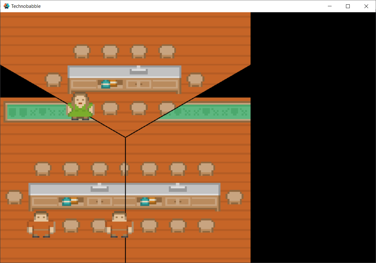
I had a feeling it might work something like this, and it turns out I was right: Adding lines to the display was as simple as substituting the desired line width (in positive and negative values) for the 0 you compared the dot products to:

if (dot(p, startVec) > 1 && -1 > dot(p, endVec))

results in:

3 Likes